
What is Arduino GUI Programmer?
Arduino GUI Programmer is a program writen in the AutoIt scripting language which provides a graphical interface (GUI) for programming the Arduino prototyping platform.
Who will use Arduino GUI Programmer?
Arduino GUI Programmer provides an easy and simple interface for those who want to use the Arduino platform in simple projects, but don't want to learn the Arduino programming language.
Why use Arduino GUI Programmer?
Arduino's GUI Programmer main advantages are:
1.Program is fully portable. No installation required, the hall program is one executable (.exe) file.
2.Doesn't require any configuration in order to start programming
3.Doesn't consist of multiple tabs and pages, everything is on one window.
4.Everything is very simple to understand and work
5.Program automatically enables, disables and updates the data of certain controls, guiding the user and preventing errors and mistakes.
Arduino's GUI Programmer main disadvantages are:
1.Program doesn't take full advantage of the Arduino's capabilities. Doesn't support serial or ethernet control
2.Program writes the generated code in a text file and doesn't upload directly to the platform, so the user must copy the generated code to the Arduino programming software before uploading.
Menu Quick Review
 - File menu: Under the "File Menu" are the following options:
1) New : Create a new project.
2) Save : Save the current project.
3) Save As : Save the current project with a different name.
4) Open : Open an existing project.
5) Exit: Quit and close the project.
 - Tools menu: Under the "Tools Menu" are the following options:
1) Boolean Calculator: A Calculator like window, by which the user can create rules by writting a Boole's expression.
2) Boolean Truth Table (2 Inputs): A GUI window for creating rules by filling up a Truth Table.
3) Boolean Truth Table (custom Inputs): A generalized version of the previous tool.
 - Help menu: Under the "Help Menu" are the following options:
1) About: Shows information for the program
2) How To: Display this Tutorial.
Pin Settings:
 In this section of the program the user can set the type of each pin by sellecting the appropriate one from a drop-down menu. There are 4 different pin types:
1) DI - Stands for "Digital Input" and can hold the values "High" or "Low". All pins can be declared as DI.
2) DO - Stands for "Digital Output" and can hold the values "High" or "Low". All pins can be declared as DO.
3) AI - Stands for "Analog Input" and can hold a value from "0" to "1024". Only pins A0, A1, A2, A3, A4, A5 can be declared as AI.
4) AO - Stands for "Analog Output" and can hold a value from "0" to "255". Only pins 3, 5, 6, 9, 10, 11 can be declared as AO.
The options available inside the combo box for each pin are the ones that the specific pin can take. Therefore it is impossible for the user to make a mistake in pin types. For example "Pin_2" cannot be set as AO or AI.
Also a unique name can be set to each pin for convenience in rule creation.
Another thing in this section is the "Submit" and the "Clear Settings" Button.
1) Submit : This button "registers" the type and name of each pin into programs memory.
2) Clear Settings: When this button is clicked another window pops, prompting the user to select an action.

- Clear UnSubmitted: This action clears all the Settings that have not yet been used in a Rule. Notice that the Settings that are in use, cannot be cleared or changed because there would be a confusion in the Rules.
- Cancel: Close the window and do nothing.
Rule Creation Methods:
A) Standard Method :
This method is accomplised by using the combo boxes at the bottom side of the Program.
 By using this method the user can take full advantage of the programs capabilities. In order to explain how to create a Rule, we must first explain what is a Rule and the parts that compose one.
What is a Rule?
Rule is an expression between inputs and output that detemines the state or value of the output. For example : "Switch Is High => Lights Is High". This is a "single input Rule" that says to turn the lights on when the switch is pressed. An example of a "dual input Rule" is: "Switch Is High AND day_sensor Is Low => Lights Is High". This Rule states that the lights would be turned on when the switch is pressed and the light sensor says that is dark.
Parts of a Rule
A Rule is composed by 7 parts.

1) Rule number : A serial number unique for each Rule. The first Rule is Rule_0, the second is Rule_1 and so on......
2) Input A : A group of combo boxes which represents the first input. An inputs is composed of three sub_parts:

- ( = equal to ) => Equal to a value
- ( > greater than ) => Greater than a value
- ( < less than ) => Less than a value
- ( >= greater/equal ) => Greater or equal to a value
- ( <= less/equal ) => Less or equal to a value
- ( <<>> compare ) => Compare to another analog pin
c) Input Value : Is the value of the input. Can be either "High", "Low", a number between 0 and 1024 and an expression when the "Compare" function is selected (further analysis in the Compare Function)
3) Inputs Comparator : A logic action between the 2 inputs (AND or OR)
4) Input B : Same as Input A.
5) Output : A group of combo boxes representing the "Output" of the Rule. Similar to the inputs, the output is composed of 3 sub_parts:
a) Output Pin: Is the pin to manipulate. Can be every pin that has been declared asDO or AO. Also there two special types of outputs :
i) Virtual_Coils : Which are , like "Virtual" Pins that can be used to store the state of multiple pins in one.
ii) Counters : Which are like "virtual" variables and can be used to count or store values.
b) Output comparator: Is the action that the Output pin will do.Can be one of the following:
- ( = equal to ) => Equal to a value
- ( f(x) expression) => Available only for AO pins. Is used to set a "depending" output Value. eq. Half of the value of an input.
- ( + Increase by ) => Increases the value of a Counter.
- ( + Decrease by ) => Decreases the value of a Counter.
- ( = Set to ) => Set the value of a Counter to a fixed value.
c) Output Value : The value or state, the Output would take. Can be either "High" or "Low" or a numeric value or an expression.
6) Delay : A numeric value that represents the time in milliseconds that the Output would delay.
7) Comments : Simple comments that the user can set for convinience.
Special Functions on Rule creation
1) Compare Function:
When the "<<>> Compare" option is selected the following window will pop.

On this window the user can select the pin to compare to, and the action for the comparison.
2) f(x) - Expression Function
When the "f(x) expression" option is selected the following window will pop.

On this window the user can select the pin to use as "base" for the value of the output.
Examples of Rule creation using the Standard Method.
A) Turn ON-OFF lights with a switch.
Two rules are required for this example:
1 - "Switch = High => Lights = High"
2 - "Switch = Low => Lights = Low"

B) Turn ON-OFF the air-condition when the temperature is over 30'C and a switch is ON.
Two rules are required for this example:
1 - "Switch = High AND temperature > 30 => air-condition = High"


Manage Projects
Arduino GUI Programmer can manage many projects which can be saved and processed at a later time.
Each project can be saved in a single (.nag) file. To save a project navigate to "File -->Save" or
"File -->Save as". To create or open an existing project navigate to "File --> New" or "File --> Open"
The name of a new project is by default "untitled". When executing Arduino GUI Programmer a new project
is by default oppened.
Set Pin Settings - Submit button
After execute Arduino GUI Programmer, user must set the "Pin Settings". Each Pin can be declared
as Digital Input (DI) or Digital Output (DO). Certain pins are able to be declared as different types also:
Pins 3,5,6,9,10 and 11 can also be declared as Analog Outputs (AO).
Pins A0,A1,A2,A3,A4,A5 can also be declared as Analog Inputs (AI).
The user can also assign a unique name to each pin, so that the pin will be easily recognisable.
Below is an example of Pin settings:

The available settings in each pin are the ones that each pin can be declared at.
If the user doesn't enter a name to a pin then the program automatically assigns one.
When user is done with Pin settings then must press the "Submit" button το register the settings.
By pressing the submit button, the program disables the declared pin, to prevent user from making
accidental changes.
Clear - Change Settings
Changes at the Pin Settings are not possible after a setting has been submitted. The reason is that
if a pin has been used in a Rule and user change it's type (from DI to DO) or it's name, the program
may crash or generate faulty results. So in order to delete-change a pin setting that has been submitted
, the so far apllied rules must be deleted as well.
When the button "Clear Settings" is clicked then another window pops up.
 The choises are:
"Clear UnSubmitted" clears the pin settings that have not yet been submited.
"Clear All" clear all the Pin Settings submitted or not. Also will clear all the rules that have been applied
so far. So the "Clear All" button basically "resets" the project.
Rule Creation
The program's Rules can be created at the "rule combos" as shown below:

When user selects the pin, which is the top of the three combos in each input, then the other 2 combos
will automatically update to give the user the appropriate options.
Changes at the values and pins are possible, also the "Clear Rule" button clears all the combo boxes
to create the rule from scratch.
After the rule is completed the "Apply Rule" button must be clicked to register the rule.
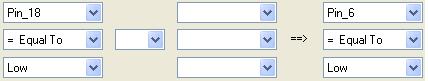
Opposite Rules
An opposite rule is a rule that functions exactly the opposite way from a given rule.
For example if a rule is :

The opposite Rule would be :

The "Auto Create Opposite Rule" Check box.
 Allows to the program to automatically create an "opposite" Rule, so that the user don't have to.
The "Auto Create...." feature works only if a new rule is apllied and not when modifying an existing one.
Modify - Delete an apllied rule
A user can modify or Delete an apllied rule by selecting the appropriate number on the "rule count"
combo and clicking on "Load Rule" or "Delete Rule" button.

After Modification the "Apply Rule" button must be clicked to register the changes.
Generate Code
After the rules are completed Press the "Generate Code" button to create a .txt file with the Arduino code. The generated file is named after the current project.
Arduino GUI Programmer is a program writen in the AutoIt scripting language which provides a graphical interface (GUI) for programming the Arduino prototyping platform.
Who will use Arduino GUI Programmer?
Arduino GUI Programmer provides an easy and simple interface for those who want to use the Arduino platform in simple projects, but don't want to learn the Arduino programming language.
Why use Arduino GUI Programmer?
Arduino's GUI Programmer main advantages are:
1.Program is fully portable. No installation required, the hall program is one executable (.exe) file.
2.Doesn't require any configuration in order to start programming
3.Doesn't consist of multiple tabs and pages, everything is on one window.
4.Everything is very simple to understand and work
5.Program automatically enables, disables and updates the data of certain controls, guiding the user and preventing errors and mistakes.
Arduino's GUI Programmer main disadvantages are:
1.Program doesn't take full advantage of the Arduino's capabilities. Doesn't support serial or ethernet control
2.Program writes the generated code in a text file and doesn't upload directly to the platform, so the user must copy the generated code to the Arduino programming software before uploading.
Menu Quick Review
1) New : Create a new project.
2) Save : Save the current project.
3) Save As : Save the current project with a different name.
4) Open : Open an existing project.
5) Exit: Quit and close the project.

1) Boolean Calculator: A Calculator like window, by which the user can create rules by writting a Boole's expression.
2) Boolean Truth Table (2 Inputs): A GUI window for creating rules by filling up a Truth Table.
3) Boolean Truth Table (custom Inputs): A generalized version of the previous tool.
1) About: Shows information for the program
2) How To: Display this Tutorial.
Pin Settings:

1) DI - Stands for "Digital Input" and can hold the values "High" or "Low". All pins can be declared as DI.
2) DO - Stands for "Digital Output" and can hold the values "High" or "Low". All pins can be declared as DO.
3) AI - Stands for "Analog Input" and can hold a value from "0" to "1024". Only pins A0, A1, A2, A3, A4, A5 can be declared as AI.
4) AO - Stands for "Analog Output" and can hold a value from "0" to "255". Only pins 3, 5, 6, 9, 10, 11 can be declared as AO.
The options available inside the combo box for each pin are the ones that the specific pin can take. Therefore it is impossible for the user to make a mistake in pin types. For example "Pin_2" cannot be set as AO or AI.
Also a unique name can be set to each pin for convenience in rule creation.
Another thing in this section is the "Submit" and the "Clear Settings" Button.
1) Submit : This button "registers" the type and name of each pin into programs memory.
2) Clear Settings: When this button is clicked another window pops, prompting the user to select an action.
- Clear All : This action clears the Settings and the applied Rules. Basically "reset's" the project.
- Clear Rules: This action clears all the applied Rules leaving the Settings as is.- Clear UnSubmitted: This action clears all the Settings that have not yet been used in a Rule. Notice that the Settings that are in use, cannot be cleared or changed because there would be a confusion in the Rules.
- Cancel: Close the window and do nothing.
Rule Creation Methods:
A) Standard Method :
This method is accomplised by using the combo boxes at the bottom side of the Program.

What is a Rule?
Rule is an expression between inputs and output that detemines the state or value of the output. For example : "Switch Is High => Lights Is High". This is a "single input Rule" that says to turn the lights on when the switch is pressed. An example of a "dual input Rule" is: "Switch Is High AND day_sensor Is Low => Lights Is High". This Rule states that the lights would be turned on when the switch is pressed and the light sensor says that is dark.
Parts of a Rule
A Rule is composed by 7 parts.

1) Rule number : A serial number unique for each Rule. The first Rule is Rule_0, the second is Rule_1 and so on......
2) Input A : A group of combo boxes which represents the first input. An inputs is composed of three sub_parts:
a) Input Pin : Is the Pin to monitor as input. Can be every pin that has been declared as DI or AI
b) Input Comparator : Is the action to examine in the pin. Can be one of the following:- ( = equal to ) => Equal to a value
- ( > greater than ) => Greater than a value
- ( < less than ) => Less than a value
- ( >= greater/equal ) => Greater or equal to a value
- ( <= less/equal ) => Less or equal to a value
- ( <<>> compare ) => Compare to another analog pin
c) Input Value : Is the value of the input. Can be either "High", "Low", a number between 0 and 1024 and an expression when the "Compare" function is selected (further analysis in the Compare Function)
3) Inputs Comparator : A logic action between the 2 inputs (AND or OR)
4) Input B : Same as Input A.
5) Output : A group of combo boxes representing the "Output" of the Rule. Similar to the inputs, the output is composed of 3 sub_parts:
a) Output Pin: Is the pin to manipulate. Can be every pin that has been declared asDO or AO. Also there two special types of outputs :
i) Virtual_Coils : Which are , like "Virtual" Pins that can be used to store the state of multiple pins in one.
ii) Counters : Which are like "virtual" variables and can be used to count or store values.
b) Output comparator: Is the action that the Output pin will do.Can be one of the following:
- ( = equal to ) => Equal to a value
- ( f(x) expression) => Available only for AO pins. Is used to set a "depending" output Value. eq. Half of the value of an input.
- ( + Increase by ) => Increases the value of a Counter.
- ( + Decrease by ) => Decreases the value of a Counter.
- ( = Set to ) => Set the value of a Counter to a fixed value.
c) Output Value : The value or state, the Output would take. Can be either "High" or "Low" or a numeric value or an expression.
6) Delay : A numeric value that represents the time in milliseconds that the Output would delay.
7) Comments : Simple comments that the user can set for convinience.
Special Functions on Rule creation
1) Compare Function:
When the "<<>> Compare" option is selected the following window will pop.

On this window the user can select the pin to compare to, and the action for the comparison.
2) f(x) - Expression Function
When the "f(x) expression" option is selected the following window will pop.

On this window the user can select the pin to use as "base" for the value of the output.
Examples of Rule creation using the Standard Method.
A) Turn ON-OFF lights with a switch.
Two rules are required for this example:
1 - "Switch = High => Lights = High"
2 - "Switch = Low => Lights = Low"
B) Turn ON-OFF the air-condition when the temperature is over 30'C and a switch is ON.
Two rules are required for this example:
1 - "Switch = High AND temperature > 30 => air-condition = High"
2 - "Switch = Low OR temperature <= 30 => air-condition = Low"
Manage Projects
Arduino GUI Programmer can manage many projects which can be saved and processed at a later time.
Each project can be saved in a single (.nag) file. To save a project navigate to "File -->Save" or
"File -->Save as". To create or open an existing project navigate to "File --> New" or "File --> Open"
The name of a new project is by default "untitled". When executing Arduino GUI Programmer a new project
is by default oppened.
Set Pin Settings - Submit button
After execute Arduino GUI Programmer, user must set the "Pin Settings". Each Pin can be declared
as Digital Input (DI) or Digital Output (DO). Certain pins are able to be declared as different types also:
Pins 3,5,6,9,10 and 11 can also be declared as Analog Outputs (AO).
Pins A0,A1,A2,A3,A4,A5 can also be declared as Analog Inputs (AI).
The user can also assign a unique name to each pin, so that the pin will be easily recognisable.
Below is an example of Pin settings:

The available settings in each pin are the ones that each pin can be declared at.
If the user doesn't enter a name to a pin then the program automatically assigns one.
When user is done with Pin settings then must press the "Submit" button το register the settings.
By pressing the submit button, the program disables the declared pin, to prevent user from making
accidental changes.
Clear - Change Settings
Changes at the Pin Settings are not possible after a setting has been submitted. The reason is that
if a pin has been used in a Rule and user change it's type (from DI to DO) or it's name, the program
may crash or generate faulty results. So in order to delete-change a pin setting that has been submitted
, the so far apllied rules must be deleted as well.
When the button "Clear Settings" is clicked then another window pops up.
"Clear UnSubmitted" clears the pin settings that have not yet been submited.
"Clear All" clear all the Pin Settings submitted or not. Also will clear all the rules that have been applied
so far. So the "Clear All" button basically "resets" the project.
Rule Creation
The program's Rules can be created at the "rule combos" as shown below:

When user selects the pin, which is the top of the three combos in each input, then the other 2 combos
will automatically update to give the user the appropriate options.
Changes at the values and pins are possible, also the "Clear Rule" button clears all the combo boxes
to create the rule from scratch.
After the rule is completed the "Apply Rule" button must be clicked to register the rule.
Opposite Rules
An opposite rule is a rule that functions exactly the opposite way from a given rule.
For example if a rule is :

The opposite Rule would be :
The "Auto Create Opposite Rule" Check box.

The "Auto Create...." feature works only if a new rule is apllied and not when modifying an existing one.
Modify - Delete an apllied rule
A user can modify or Delete an apllied rule by selecting the appropriate number on the "rule count"
combo and clicking on "Load Rule" or "Delete Rule" button.

After Modification the "Apply Rule" button must be clicked to register the changes.
Generate Code
After the rules are completed Press the "Generate Code" button to create a .txt file with the Arduino code. The generated file is named after the current project.
Δεν υπάρχουν σχόλια:
Δημοσίευση σχολίου